
I just bought an Adaptronic e420c ECU and now I'm ready to install it...
...
ECU installed and working!
The e420c manual is very detailed, and when some doubts remain there is the Forum to put your questions: Andy, Cory and the users will certainly answer.
Below some infos that can be useful for others Fiat owners to do the same work.
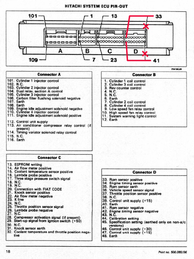
My Fiat 1.8 16V mounts an Hitachi ECU and the conversion with the Adaptronic one is quite easy.
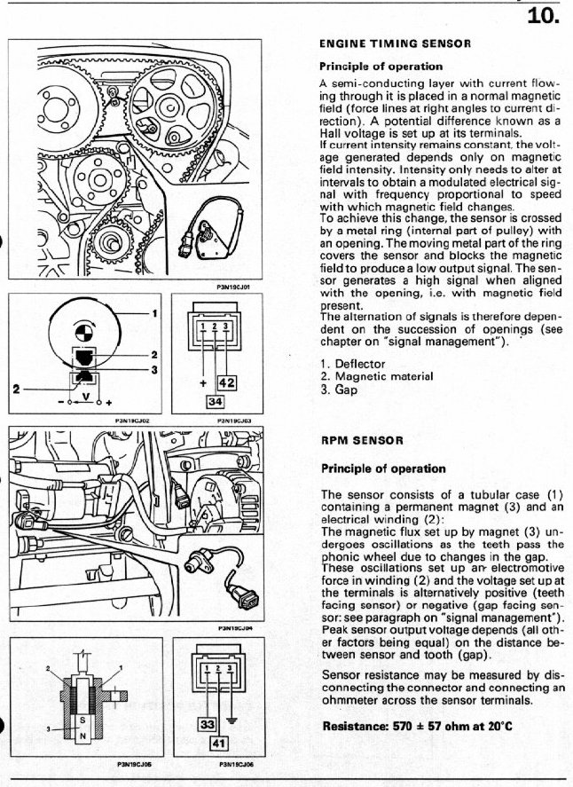
These are the sensors for timing (hall, on cam) and RPM (reluctor, on crank):
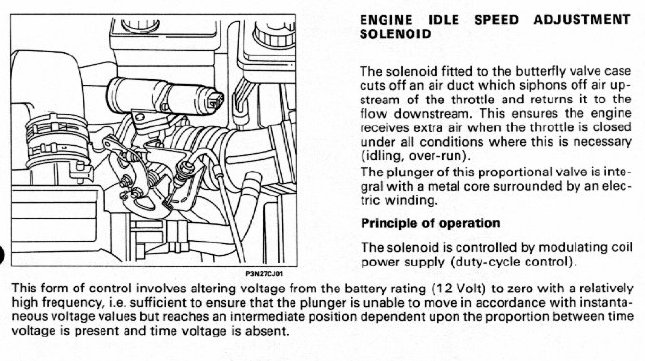
Here a few info about idle solenoid, that is PWM controlled:
Clic here to view the wiring diagram of the Adaptronic E420C (pdf, 530 kb)
Well, you can do a clean installation simply by connecting the wires coming out from Adaptronic to those of your standard harness, according to this scheme:
| Adaptronic pin number | Hitachi pin number |
|---|---|
| J1 - 1 | Connector A - 112 |
| J1 - 2 | Connector A - 107 |
| J1 - 3 | Connector A - 108 |
| J1 - 4 | Connector A - 116 |
| J1 - 5 | Connector A - 103 |
| J1 - 6 | Connector A - 101 |
| J1 - 7 | Connector A - 105 |
| J1 - 8 | Connector A - 110 |
| J2 - 1 | Connector A - 113 (air conditioner relay) |
| J2 - 2 | Connector A - 109 (idle solenoid) |
| J2 - 3 | Connector A - 106 (purge solenoid) |
| J2 - 4 | Connector A - 114 (timing variator solenoid VVT) |
| J2 - 5 | Connector B - 12 |
| J2 - 6 | Connector D - 40 and 48 |
| J3 - A1 | free (dig. in) |
| J3 - A2 | free (dig. in) |
| J3 - A3 | free (dig. in) |
| J3 - A4 | free (dig. in) |
| J3 - A5 | free (I connected analog wide band O2 signal) |
| J3 - A6 | Connector C - 16 (EGO), connect 26 to shield to gnd |
| J3 - A7 | not present, connect positive wire of your MAT |
| J3 - A8 | not present, connect positive wire of your MAP |
| J3 - A9 | not present, connect negative wire of your MAP |
| J3 - A10 | Connector C - 25 |
| J3 - A11 | free (dig. in) |
| J3 - A12 | free (dig. in) |
| J3 - A13 | free (dig. in) |
| J3 - A14 | Connector C - 28 (A/C activation) |
| J3 - A15 | Connector C - 21 (KNOCK), connect 31 to shield to gnd |
| J3 - A16 | free (aux temp) |
| J3 - A17 | Connector C - 15 |
| J3 - A18 | not present, connect signal wire of your MAP |
| J3 - A19 | Connector D - 37 |
| J3 - A20 | Connector C - 32 |
| J4 - B1 | none (ignition3/tacho) |
| J4 - B2 | Connector B - 2 and 7 (wasted spark) |
| J4 - B3 | none |
| J4 - B4 | Connector D - 41 (white intern.) and 35 (shield) |
| J4 - B5 | Connector D - 42 |
| J4 - B6 | none |
| J4 - B7 | Connector B - 10 |
| J4 - B8 | Connector B - 9 |
| J4 - B9 | Connector B - 1 and 8 (wasted spark) |
| J4 - B10 | none |
| J4 - B11 | Connector D - 33 |
| J4 - B12 | none |
| J4 - B13 | Connector D - 34 |
| J4 - B14 | Connector D - 36 |
| J4 - B15 | free (Aux out) |
| J4 - B16 | Connector A - 104 (fuel pump) |
but always remember that the numbers sequence of Hitachi-Connector D is wrong: it starts from left to right and not opposite like the original picture shows (see above on this page the Hitachi pin out).